


TYPICAL PRESSURE & VACUUM MF & UF MEMBRANE SYSTEMS
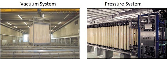
Figures PD.5 and PD.6 show typical pressure-driven and vacuum drive hollow-fiberHollow-fibers: In hollow-fiber membranes, the membrane consists of a long spaghetti-like tube with a hollow core. The fibers are bundled together with the open ends encased in a resin. Flow can pass through the membrane either from the outside into the hollow membrane center or from the inside to the outside. Hollow fibers are typically used in microfiltration (MF) and ultrafiltration (UF) membrane processes. MFMicrofiltration (MF) membranes: Microfiltration membranes are typically hollow-fibers with a pore size range of approximately 0.1 – 0.2 μm (nominally 0.1 μm)./UFUltrafiltration (UF) membranes: Ultrafiltration membranes are typically hollow-fibers with a pore size range of approximately 0.01 – 0.05 μm (nominally 0.01 μm). systems. Note that in the vacuum systemVacuum systems: Vacuum membrane systems are microfiltration or ultrafiltration systems in which the membranes are immersed in a tank of water and a vacuum applied to pull the water through the membrane., the water concentratedConcentrate: Concentrate refers to the waste stream created in reverse osmosis and nanofiltration systems or any membrane system in which not all the feed water passes through the membrane. The water that does not pass through the membrane will have a much higher concentration of dissolved solids and/or particulates. with particulates can be discharged continuously or intermittently from the basin as mentioned previously.
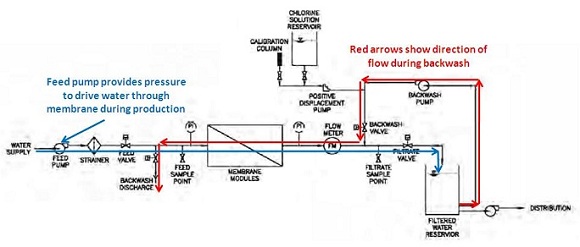
Figure PD.5 Schematic of a Typical Pressure-Driven Hollow-Fiber (MF/UF) System (USEPA, 2005)
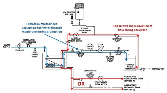
Figure PD.6 Schematic of a Typical Vacuum-Driven Hollow-Fiber (MF/UF) System (USEPA, 2005)


