MFMicrofiltration (MF) membranes: Microfiltration membranes are typically hollow-fibers with a pore size range of approximately 0.1 0.2 µm (nominally 0.1 µm). and UFUltrafiltration (UF) membranes: Ultrafiltration membranes are typically hollow-fibers with a pore size range of approximately 0.01 0.05 µm (nominally 0.01 µm). membranes are either flat sheets which are wound in a spiral or hollow fiberHollow-fibers: In hollow-fiber membranes, the membrane consists of a long spaghetti-like tube with a hollow core. The fibers are bundled together with the open ends encased in a resin. Flow can pass through the membrane either from the outside into the hollow membrane center or from the inside to the outside. Hollow fibers are typically used in microfiltration (MF) and ultrafiltration (UF) membrane processes. with the latter being more common for MF and UF systems. The membrane allows water to pass through it but presents a barrier for particles larger than the membrane pore sizes which range from about 0.1-0.2 µmµm: A µm stands for one micrometer (or micron) which is a unit of length equal to one millionth of a meter. for MF membranes and 0.001-0.05 µm for UF membranes. Some prefer to think of the UF pore sizes in terms of the lower end of the molecular weight of macromoleculesMacromolecules: Macromolecules are typically large molecular weight organic molecules, e.g., polymers and humic materials. They occur naturally but many are also manmade with defined chemical and size properties. they can remove which is about 10,000-500,000 DaltonsDaltons: A Dalton is a unit of mass equal to 1/12th the mass of a carbon-12 atom (i.e., one atomic mass unit. (amu)).. Importantly, the removal mechanism for MF and UF membranes is more complex than simple sieving since particles smaller than the pore size can be removed. These mechanisms include interception of particles through the depth of the membrane, electrostatic repulsion, adsorption, and formation of a cake on the membrane surface. A compromise of a membrane module's integrity can of course negate the filter efficiency and allow significant amounts of particulates to pass.
Figures PD.2 and PD.3 show the basic configurations of hollow fiber (most common for MF and UF systems) and spiral-woundSpiral-wound: Spiral-wound membranes is a configuration in which sheets of a semi-permeable membrane, a porous support matrix, and a spacer are wrapped around a central filtrate collector tube. They are typically associated with nanofiltration (NF) and reverse osmosis (RO) membrane processes. membranes. Although there are variations on how a spiral-wound membrane is constructed, generally it is a sandwich of flat layers consisting of 1) a spacer layer through which the feed waterFeed water: The feed water is the water stream applied to the membrane unit. flows, 2) the membrane, and 3) a layer through which the treated water (i.e., the "permeatePermeate: Permeate is synonymous with filtrate but is typically used with reverse osmosis and nanofiltration systems." or filtrateFiltrate: Filtrate is the water that has passed through the membrane.) flows. This sandwich is wrapped into a spiral around a central collection tube. The feed water flows parallel to the tube and becomes the "concentrateConcentrate: Concentrate refers to the waste stream created in reverse osmosis and nanofiltration systems or any membrane system in which not all the feed water passes through the membrane. The water that does not pass through the membrane will have a much higher concentration of dissolved solids and/or particulates.", i.e., the rejected water that has a much higher concentration of particulates. The permeate flows perpendicular to the concentrate and flows radially inward to the central tube. A hollow fiber is simpler to visualize since the membrane is a hollow tube and the water can flow either from the outside to the inside or from the inside to the outside of the membrane. The MF or UF membrane material itself is invariably a synthetic polymer such as cellulose acetate (CA), polyvinylidene fluoride (PVDF), polyacrylonitrile, polypropylene, polysulfone (PS), polyethersulfone (PES), or another polymer. The choice of material is a function of desired mechanical strength, resistanceResistance: Resistance or membrane resistance is a measure of the difficulty of passing water through a membrane due to the nature of the membrane itself or to foulants accumulated on the membrane surface. to oxidants such as chlorine, surface charge, and hydrophobicityHydrophobicity:
Hydrophobicity is the property of being water-repellent. In contrast, hydrophilicity is the property of having a strong affinity for water. The hydrophilic and hydrophobic properties of a membrane material are related to the surface tension of the material. The higher the surface tension value of the material, the more hydrophilic the material is. The degree of hydrophilicity or hydrophobicity influences the wettability and applied pressure requirements for water flow through the membrane. Hydrophilic membranes require less operating pressure than hydrophobic membranes.. Several potential membrane cross-sections are shown in Figure PD.4 although most MF and UF membranes are either symmetric or asymmetric.
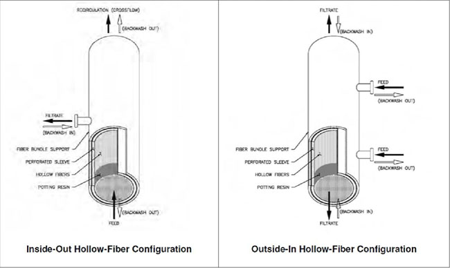
Figure PD.2. Inside-Out and Outside-In Modes of Operation (Using Pressure Vessels) (USEPA, 2005)
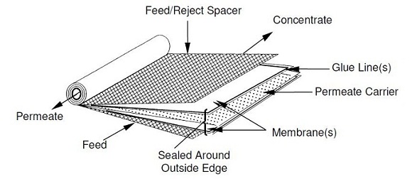
Figure PD.3. Spiral-Wound Membrane Module (USEPA, 2005)
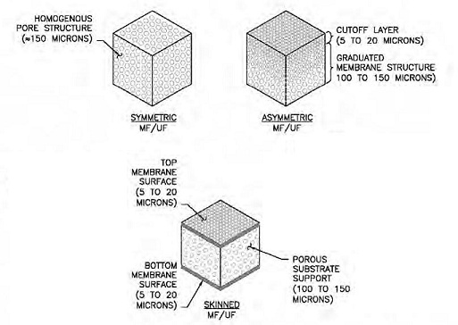
Figure PD 4. MF and UF Membrane Construction and Symmetry (USEPA, 2005)
MF and UF Hollow-Fiber Membrane Modules. Since most MF and UF membrane systems use hollow-fibers, only these types of systems will be discussed herein. The fibers themselves are generally about 1-2 m long, outside diameter of 0.5-2.0 mm, fiber wall thickness of 0.1-0.6 mm, and inside diameter of 0.3-1.0 mm. The fibers are usually bundled together lengthwise and encased in resin on both ends with the inner fiber cores open on one or both ends. These modules are typically arranged in one of three ways:
1) enclosed in a pressure vessel that is part of the overall hollow-fiber module and usually mounted vertically,
2) inserted into a separate pressure vessel that is usually horizontal, or
3) the bundled hollow-fibers are suspended and submerged vertically in a basin that is not pressurized in which case a vacuum draws the water through the membrane from the outside or a pressure forces the water through the membrane from the inside.
Flow through the membranes can be either pressure-drivenPressure system: A pressure membrane system applies a pressure to the feed water side of the membrane in order to force the water through the membrane. or vacuum-drivenVacuum systems: Vacuum membrane systems are microfiltration or ultrafiltration systems in which the membranes are immersed in a tank of water and a vacuum applied to pull the water through the membrane. and can be either direction through the membrane although a flow from the outside-in is less subject to plugging and increases the membrane filtration area. Operating pressures generally range from 3-40 psi. A typical module of several hundred to thousands of membranes was shown previously in Figure PD.2. Usually there is only two streams, an input stream and an output stream, i.e. there is not usually a continuous concentrate stream as is typical with reverse osmosis (RO)Reverse osmosis (RO): Reverse osmosis is the reverse of the natural osmosis process, i.e., the passage of a water through a semi-permeable membrane from a solution of higher concentration of dissolved solids to a solution of lower concentration. Reverse osmosis applies a high pressure on the higher concentration side of the membrane to drive water through the membrane against the concentration gradient, in order to produce a water with a lower concentration of dissolved solids. although concentrate can be discharged intermittently or continuously from a vacuum-driven system. A single constructed membrane modules including associated piping and valving and which typically can be isolated from the rest of the system is called a rack, train or skid. Membrane systems are also invariably proprietary with the manufacturer providing most if not all of the complete treatment system and also determining operational aspects such as backwashingBackpulse or backwash: 1) Backwash is a procedure in which periodically the flow direction is reversed through the membrane for a short period of time in order to remove particulates accumulated at the membrane surface. 2) Backwash also refers to the waste water produced as a result of the backwash procedure., chemical cleaningClean-in-place (CIP) or in-situ chemical cleaning: Clean-in-place is a procedure performed periodically to clean a membrane more thoroughly than backwashing can achieve in order to restore the permeability of the membrane towards baseline levels. The process uses chemicals such as citric acid and chlorine or others to remove accumulated foulants on the membrane., and integrity testing.